


 Leeds
Leeds Doncaster
 Sheffield
 Bradford
 Hull
Hull Halifax
 Sunderland
 Newcastle
 Middlesborough
 Yorkshire Moors
 Teesside
 Cumbria
 Harrogate
 York
York Yorkshire Dales
 Northumberland
 Goole
Goole Carlisle
 Keswick
 Kendal
 Barrow-in-Furness
 Lancaster
 Blackpool
 Morecambe
 Southport
 Liverpool
 Wigan
Wigan Manchester
 Blackburn
 Burnley
 Forest of Bowland
 Oldham
 Chester
 Stockport
 Peak District
 Skipton
 Crewe
Crewe Rotherham
 Stoke
Stoke Driffield
Civil engineering decisions rely on accuracy, certainty, and consistency.
Surveying for Civil Engineers.
One Trusted Partner.
Survey Data That Engineers Can Design From.
Survey Data That Engineers Can Design From.
Civil engineers need survey data that is accurate enough to engineer from — not approximate enough to sketch from. That distinction matters when the structural engineer interrogates the foundation level, when the drainage designer checks the fall, when the machine control operator loads the earthworks model, when the setting-out engineer places the first peg. At every stage, the survey data either supports the engineering or it undermines it.
Site Surveying Services has been delivering survey to civil engineering teams across Lancashire, the North West and nationally since 1997. We understand the design process, we understand what the data needs to do at each project stage, and we deliver to the accuracy specification the engineering requires — not the accuracy specification that was easiest to produce.
We work with consulting engineers, design and build contractors, infrastructure consultants, highways engineers and major civils contractors. If your programme is in our territory — or anywhere in the UK — the team below is ready.
Survey at every stage of the civil engineering design process
Feasibility and options appraisal
At feasibility stage, the survey brief needs to serve the options appraisal — capturing enough information to compare scheme options, identify constraints and establish the engineering parameters that will govern the preferred option. Over-specifying at this stage wastes budget on data the feasibility cannot use. Under-specifying produces an options appraisal based on assumptions that the detailed design will later contradict.
What is typically needed at feasibility:
Topographic survey of the study corridor or site area — ground levels, significant features, drainage, watercourses, boundaries and contextual detail. UAV survey for large areas, long corridors or terrain where ground-based survey alone is impractical. Desktop utility search to establish the service risk environment before intrusive works are committed to. Bathymetric survey where the feasibility area includes watercourses, culverts or coastal features.
The questions that matter at this stage:
What is the study area extent — and does the survey need to extend beyond the likely scheme boundary to capture the constraint context? What accuracy is needed for feasibility levels — 1:2500 context or 1:500 engineering accuracy? Does the terrain include vegetation that will obscure ground-based GPS, requiring UAV LiDAR for accurate DTM production? Is there a watercourse within the study area that needs a bathymetric baseline?
What we deliver:
OS-controlled topographic survey to the accuracy and extent the feasibility requires. UAV LiDAR and photogrammetry where appropriate. Bathymetric survey of watercourses within the study area. Desktop utility records. All data georeferenced to OS National Grid and tied to Ordnance Datum Newlyn.
Survey at every stage of the civil engineering design process
Preliminary and developed design
At preliminary design stage, the survey data needs to be accurate enough to fix the scheme alignment, establish the earthworks envelope, design the drainage strategy and produce the preliminary cost estimate with confidence. The difference between a survey that was produced to planning accuracy and one that was produced to engineering accuracy is not visible in a drawing — it appears in the discrepancies between design and construction that produce variations the client cannot understand.
What is typically needed at preliminary design:
Full topographic survey to engineering accuracy — typically ±20–50mm on levels and ±50mm on planimetric features for preliminary design. For drainage design, tighter accuracy on drainage features, channel beds and outfall levels. For earthworks, accurate existing ground levels across the full works extent. PAS 128 utility mapping to Quality Level C minimum — detection survey confirming what is likely to be present before the design fixes service crossings and diversions. Control network to the accuracy the scheme requires.
The questions that matter at this stage:
Has the survey been produced to engineering accuracy or planning accuracy — and is the distinction documented? Are the utility records produced to PAS 128 standard — and to which quality level? Has the coordinate system been agreed with the structural engineer and drainage designer? Are the level data sufficient for accurate earthworks quantification?
What we deliver:
Topographic survey to engineering accuracy specification. PAS 128 utility mapping to Quality Level C or B as appropriate. Primary control network installation and verification. All data in AutoCAD DWG or the CAD format your design software requires. Coordination of the survey datum with structural and drainage design teams.
Survey at every stage of the civil engineering design process
Detailed design
At detailed design stage, the survey data underpins the construction information. Foundation levels, drainage gradients, structural positions, pavement construction depths, kerb lines — all determined by the survey. If the ground levels from preliminary design are inadequate for detailed drainage design, if the utility positions from the QLC survey are not physically verified where critical crossings occur, if the control network accuracy is insufficient for setting-out tolerance — these are not hypothetical risks. They are programme and cost events that occur when the survey specification was not matched to the design stage it needed to serve.
What is typically needed at detailed design:
Updated topographic survey where significant time has elapsed since the preliminary survey, or where the design has evolved to require data not captured previously. PAS 128 utility mapping to Quality Level A at critical service crossing and diversion locations — physical verification of depth, position and material at the points where the design cannot afford uncertainty. Secondary control network at the accuracy the setting-out tolerance requires. BIM-ready survey data where the project has an EIR.
The questions that matter at this stage:
Are service positions physically verified at the critical design locations — or are they inferred from QLC detection? Is the control network accuracy specification matched to the setting-out tolerance in the contract? Has the BIM requirement and EIR been agreed with the survey team before the detailed survey scope was fixed?
What we deliver:
Updated topographic survey to detailed design accuracy. PAS 128 Quality Level A at critical locations — physical verification using vacuum excavation. Secondary control network to setting-out specification. BIM-ready data to your EIR at the LOD specified. All in-house, by the same team.
Survey at every stage of the civil engineering design process
Construction
During construction, the survey function shifts from supporting design to supporting the contractor — but the civil engineer’s responsibility for the design data does not end when the contractor arrives on site. Setting-out errors discovered during construction are design responsibility until it is established that they resulted from setting-out error rather than design error. Monitoring of structures adjacent to excavation is a design obligation that continues throughout the construction programme. As-built survey is the record that the engineer signs off.
What is typically needed during construction:
Setting-out engineers for complex structure positions, drainage, highway geometry and earthworks. 3D machine control for bulk earthworks — reducing setting-out time, improving accuracy and tracking earthworks progress against design volumes. Monitoring of adjacent structures, utilities and infrastructure where excavation depth or proximity creates movement risk. As-built survey at programme stages to verify construction compliance with the design.
What we deliver:
Directly employed setting-out engineers with over 600 setting-out programmes delivered in 2025. 3D machine control model creation and calibration for bulk earthworks. Structural and settlement monitoring with trigger level reporting. As-built survey in CAD format for design compliance verification. UAV survey for earthworks progress recording and volumetric reconciliation.
Survey at every stage of the civil engineering design process
Post-construction and handover
The as-built survey at handover is the record of what was built — and for the civil engineer, it is the document that closes out the design liability and provides the infrastructure owner with the baseline data for asset management. A well-produced as-built survey resolves the questions that arise at handover. A poorly produced one creates them.
What is typically needed at handover:
As-built topographic survey of the completed works — confirming earthworks levels, drainage inverts, structure positions and all built features against the design. Bathymetric survey at watercourse crossings and culverts if required for handover documentation. Updated monitoring records confirming the condition of adjacent structures at scheme completion.
What we deliver:
As-built topographic survey to the specification agreed with the client and infrastructure owner. Bathymetric survey of watercourse features. Final monitoring reports and condition records. All data georeferenced and delivered in the format the asset management system requires.
Surveying Services
Most Used by Civil Engineers.
Surveying Services Most Used by Civil Engineers.
Measured building surveys
Floor plans, elevations, sections and 3D models for all existing structures involved in the development.
Topographic survey
OS-controlled survey at every design stage, to the accuracy the stage requires. Ground levels, drainage, boundaries, context and all features the engineering depends on.
Control network installation
Primary and secondary control to the accuracy specification the programme requires. The foundation every downstream survey activity depends on.
Setting-out engineers
directly employed engineering surveyors for construction programmes of any scale. Over 600 setting-out projects in 2025.
BIM model creation
Survey data to your EIR at the LOD specified. In-house from capture to model.
UAV survey
Large area topographic survey, earthworks progress recording and volumetric reconciliation. LiDAR and photogrammetry from our CHCNAV X500 platform.
PAS 128 utility mapping
Physical verification of underground services where the design cannot afford uncertainty about what is below.
Bathymetric Survey
survey for civil engineers North West
Case Studies: Survey Data in practice
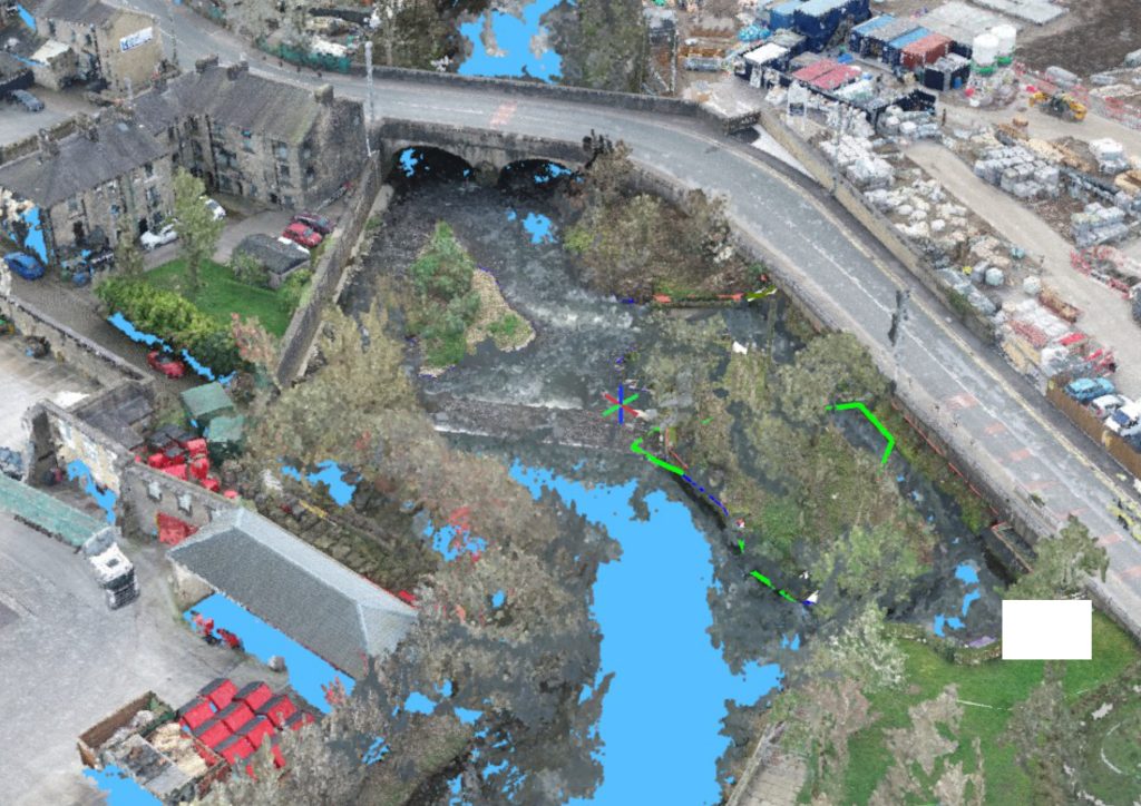
Comprehensive Infrastructure Surveying — Ilkley
Full PAS 128 and topographic survey package for a live infrastructure scheme — all services located, verified and plotted alongside detailed ground and drainage data, delivered as a single coordinated georeferenced dataset. The design team had everything they needed from one instruction, one team and one output.
Case Studies: Survey Data in practice
BAE Systems — Barrow-in-Furness
Why choose site surveying services
On site. On spec. On time.
We support civil engineers across the UK by delivering accurate, reliable survey data that stands up to technical scrutiny and real-world application across the full project lifecycle. Our surveys provide the robust, dependable information required to design, coordinate, and deliver infrastructure with confidence.
At Site Surveying Services, we understand the analytical and technical demands placed on civil engineering teams. We work closely with consulting engineers, infrastructure designers, and project teams to deliver survey data that aligns with engineering standards, design methodologies, and regulatory requirements. From early feasibility through detailed design and construction support, our approach is tailored to each scheme.
Our experience supporting civil engineering projects allows us to anticipate the level of detail required at every stage. Whether informing drainage design, highways and utilities coordination, earthworks modelling, or structural interfaces, we deliver clear, precise survey outputs that integrate seamlessly into engineering calculations, drawings, and BIM environments.
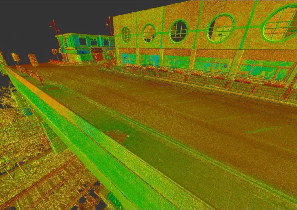
We provide engineering and land surveying services across a wide range of sectors and site conditions, from constrained urban infrastructure to large linear and multi-disciplinary schemes. Our topographical surveys, control networks, and point cloud data give engineers confidence that designs are based on accurate, verifiable site information.
Quality, communication, and consistency are central to our service. By combining technical surveying expertise with a strong understanding of civil engineering workflows, we help ensure projects progress efficiently from design through to construction. For civil engineers seeking a dependable surveying partner, we provide the data that supports technically sound and deliverable solutions.
fast turnaround
Get a quick quote and a survey team prepared for instruction. When the programme window opens, we're ready.
Industry Accredited
Built on recognised industry standards. Constructionline Gold accredited, CAA Approved, CDM 2015 compliant, and surveys delivered to PAS 128
Nationwide
Coverage across the UK with local knowledge you can rely on. Headquartered in Clitheroe, we know the sites, the contractors and the programmes — backed by the capability to deliver anywhere.
Programme-Critical
Data that works in your environment from day one. BIM to your EIR. CAD to your spec. No reprocessing. No delays to the design team.
Frequently Asked Questions
Frequently Asked Questions
What accuracy specification should I require for a civil engineering topographic survey?
Accuracy specification depends on the design stage and the engineering activities the data needs to support. For feasibility and options appraisal, ±50–100mm on levels is typically sufficient. For preliminary design, ±20–50mm. For detailed design and drainage, ±10–20mm on levels and ±20–50mm on planimetric features. For setting-out control, ±5–10mm. The accuracy specification should be agreed between the engineer and the survey team before the survey scope is fixed — and it should be documented in the survey specification and confirmed in the methodology statement delivered with the data. If you are not sure what accuracy your design stage requires, ask us. It is one of the most common questions we are asked and the answer depends on how the data will be used downstream.
What is the right PAS 128 quality level for a civil engineering scheme?
Quality Level C — active detection using GPR and EML, no physical verification — is appropriate for preliminary design and feasibility where service positions need to be understood but are not yet being designed around precisely. Quality Level A — physical verification at test points using vacuum excavation — is required at detailed design stage wherever the design fixes a service crossing, a diversion, a structure foundation or any element where the wrong assumption about service depth or position would produce a variation. For highway schemes, the combination of QLC for the full corridor and QLA at structure positions and critical crossings is the standard approach. We advise on the right quality level distribution for your specific scheme at the time of instruction.
What accuracy does a setting-out control network need to achieve?
The control network accuracy specification needs to match the setting-out tolerance in the construction contract. For most civil engineering applications — highway construction, drainage, earthworks, structural foundations — ±10–20mm in plan and ±5–10mm in height is appropriate. For rail and airport works, tighter tolerances of ±3–5mm in plan and ±2–3mm in height may be required. The control specification should be agreed with the structural engineer and the setting-out team before the network is installed — not discovered to be inadequate when the first structure position is checked. We confirm achievable accuracy for your site conditions and instrumentation at the time of scoping.
What survey data does a hydraulic model require?
A hydraulic model requires topographic survey of the flood plain and valley corridor — at the density and accuracy needed to produce a reliable DTM for the modelling domain — and bathymetric survey of the watercourse cross-sections at the spacing the model requires. For 1D models, cross-section data at agreed chainages along the modelled reach, delivered in HEC-RAS, InfoWorks ISIS or EACSD format. For 2D models, a continuous DTM of the full flood plain domain, at a resolution appropriate for the model cell size. Water surface levels at the time of survey, confirmed to OS Datum, for model calibration. We produce EA-compliant bathymetric and topographic data for hydraulic models and confirm the deliverable format with the modelling engineer at the time of instruction.
How do I specify BIM survey data for a civil engineering project?
The starting point is the Employer’s Information Requirements — the EIR defines what the model must contain, how it must be structured and in what format it must be delivered. The key information we need from the EIR before scoping the survey: the required LOD, the Revit version or platform, the coordinate system and level datum, the naming and layer convention, and whether federated model requirements mean the survey model needs to coordinate with structural and MEP models from other disciplines. The survey scope is built around the EIR from the first conversation — not adapted to it at handover. If the project does not yet have a finalised EIR, we can advise on what the EIR should specify for civil engineering survey data at each design stage.
What is the difference between a DTM and a DSM — and which do I need for civil engineering design?
A Digital Terrain Model (DTM) represents the bare earth surface — vegetation and above-ground structures removed. A Digital Surface Model (DSM) includes vegetation heights and structure. For civil engineering design — earthworks, drainage, highway alignment, flood modelling — you need a DTM. The bare earth surface is what the engineering is built on. A DSM that includes tree canopy heights as part of the ground elevation model will produce earthworks calculations and drainage gradients that do not reflect the actual ground. From UAV LiDAR data, we produce both DTM and DSM and confirm which is required for your specific application at the time of instruction.
Can you deliver survey data in a format compatible with civil engineering design software?
Yes. We deliver topographic and survey data in AutoCAD DWG and DXF as standard — compatible with Civil 3D, MicroStation, 12d Model and all major civil engineering design platforms. For BIM projects, we deliver in Revit or IFC format. For hydraulic modelling, we deliver cross-section data in HEC-RAS, InfoWorks ICM and ISIS format as standard. For GIS applications, we deliver in formats compatible with QGIS and ArcGIS. If your design software requires a specific file format, layer structure or coordinate system, confirm this at the time of instruction and we will build it into the deliverable specification.
Do you provide setting-out support as well as survey?
Yes — and this is one of the most important things that distinguishes Site Surveying Services from a survey-only firm. Our directly employed setting-out engineers provide on-site support for construction programmes of any scale across Lancashire and the North West. They work from 2D CAD drawings and 3D design models, check design data for consistency before setting out begins, flag conflicts between the design and existing ground conditions, and provide as-built verification at programme stages. In 2025 we delivered over 600 setting-out and site engineering programmes. The surveyor who produced the design survey and the engineer setting out on site are the same organisation — which means the spatial knowledge of the site is consistent throughout the programme.
What monitoring is required adjacent to excavation on a civil engineering scheme?
The monitoring requirement adjacent to excavation is determined by the structural engineer or geotechnical engineer based on the excavation depth, the proximity to sensitive structures or infrastructure, the ground conditions and the acceptable movement thresholds in the design. Typically, monitoring is specified for any excavation within the influence zone of existing structures — roughly 1.5 to 2 times the excavation depth — and for any excavation adjacent to live utilities, heritage structures or infrastructure that cannot be disturbed. We deliver structural and settlement monitoring to the trigger levels and monitoring frequency specified in the geotechnical design — with immediate reporting when readings approach or reach threshold levels. If monitoring has not yet been specified and you need advice on what is appropriate for your scheme, we will advise at the time of enquiry.
Do you work with the Environment Agency supply chain?
Yes. We hold Constructionline Gold, PAS 128 accreditation, RICS regulation and CDM compliance — the standard accreditation profile for EA framework supply chains. We deliver topographic and bathymetric survey data to EA standards for flood risk, river management and asset maintenance programmes across the North West and nationally. We are familiar with EA data submission requirements and produce survey outputs that integrate directly with flood modelling software without reprocessing.